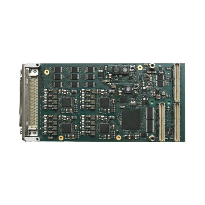
PMC with 8/16 Voltage / Current D/A and 20x LVTTL/TTL I/O
SKU:
TPMC542
Fabrikant:
Tews
- I/O Type : Analog I/O
- Type Mezzanine : PMC
Tews TPMC542 16/8 Channel Voltage & Current Range D/A and 20 Channel LVTTL/TTL Digital I/O
Details
More Information
Downloads
Tews PMC Module for Multi-function I/O
The TPMC542 is a standard single-wide PCI Mezzanine Card (PMC) compatible module providing 16 or 8 channels of simultaneous update single-ended unipolar/bipolar 16bit analog output and 20 channels of tristate capable 5V-tolerant LVTTL/TTL digital input/output.A 32 bit 33 MHz PCI interface is provided at the PMC P11 and P12 connectors. The digital I/O signals and analog output signals are accessible via a Mini D Ribbon (MDR68) type front I/O connector.
For each individual D/A channel, the following output ranges are configurable:
• 0V to 5V Voltage Range
• 0V to 10V Voltage Range
• ±5V Voltage Range
• ±10V Voltage Range
• 4mA to 20mA Current Range
• 0mA to 20mA Current Range
• 0mA to 24mA Current Range
Additionally, for each Voltage Range a 20% over-range may be enabled.
The TPMC542 provides a D/A Sequencer unit for periodic simultaneous digital to analog conversions at a configurable conversion rate. In sequencer mode, the D/A conversion data is fetched from buffers in host memory by PCI master DMA transfer and is temporarily stored in an on-board data buffer. The Sequencer provides a Frame Mode used for repetitive frames of simultaneous D/A conversions upon an appropriate frame trigger signal event.
Conversion clock (conversion rate) and frame trigger signals may be generated on-board for internal use and may also be driven out on P14 rear I/O if the card is operating as a master card in a Multi-Board configuration. The conversion clock (conversion rate) and frame trigger signals may also be sourced externally via the P14 rear I/O interface if the card is operating as a target card in a Multi-Board configuration.
Each TPMC542 is factory calibrated. The correction data is stored in an on-board serial EEPROM unique to each PMC module. These correction values may be used to perform a hardware correction for every D/A channel and output range.
The digital I/O lines are ESD protected. Each digital I/O line has a dedicated line transmitter with individual output enable control and a dedicated line receiver. The line receivers are always enabled, so the digital I/O line level can always be monitored. Each digital I/O line input is capable of generating an interrupt triggered on rising edge, falling edge or both.
Additionally, a debounce filter can be configured to get rid of bouncing on the digital I/O inputs. Each digital I/O line has a 4.7k& pull resistor to a common reference. The common pull resistor reference is programmable by software (one setting for all digital I/O lines) to +3.3V, +5V or GND.
|
|

